Step 2 - Removing the main board from the case
Now the top of the RF shielding is off you need to remove the board from the case as we need to be able to get at the bottom of the boards to desolder the
ROM. First you will need to remove the 4 screws holding the PCB to the case. These are easy enough to locate. 1 either side of the cartridge port
and 2 near the joypad ports.
Once you have unscrewed them (putting them in a safe place also) gently lift out the main board. If you have a system with no modulator this will be
pretty easy, for the rest of you it will be quite awkward to remove. It is a very snug fit and you don't want to bend the board too much. One thing to try is
to use a flat bladed screw driver to pry the edge out of the shielding near the ports, another aproach is to bend the shielding slightly. Just take your time and be careful.
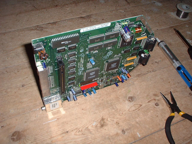
Once out you can move the case and put the board down on a suitable surface (free from static.) .
Easy eh :) you are now ready to get that soldering iron hot. You need it hot enough to melt the solder on the board, so give it a few minutes to warm up.
Now if you look at the underside of the mainboard you should be able to find the pins that relate to the boot ROM quite easily. I find the easies t way to
desolder chips is to place the board on its edge, so you can apply heat from one side whilst sucking the solder from the other. This gets all the solder
out of those nooks and crannies. Here is a picture of the board on it's edge ready to have the ROM desoldered:
step 3 - Desoldering the ROM
As you can see the ROM is at the top most edge, this makes getting at the pins easier. This is also where your spare pair of hands comes in to hold the
PCB in this orientation without too much pressure being put on the edge. Also if you use the same technique as me (wedge it between the floor boards :) )
Make sure that the board isn't resting on the components.
Copyright Graeme Hinchliffe 2003